
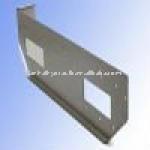
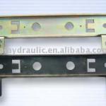
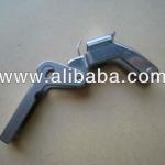
RG Linear drive linear guide rails
| Place of Origin:Zhejiang China (Mainland) | Brand Name:GP | Model Number:GP0346 | Type:Machining Parts |
| Material:Stainless steel | Plating:Zinc |

The GP rolling ring driveassembly is uniquely suited for Wire, Cable ,Fiber optic Level Winding system, Scanning Equipment ,Scanning Machinery , Spraying Equipment ,Spraying Machinery, Slitter Rewinders , Packaging Equipment and Converting Machinery
The linear speed (pitch) of the traverse and the travel direction are bothmechanically controlled - independently of the drive motor. This eliminates the need for electronics and programming to save money and simplify set-up and operation.
A GP traverse winding assembly does not require a separate drive motor. Instead, the GP shaft is linked via a simple pulley system to the take-up spool shaft.
Once the linear pitch is set on the GP traverse winding unit, it remains automatically synchronized with the rotating spool, even if the take-up motor speeds up or slows down. There is never a need to change gears or reverse the motor.
System showing :
A GP rolling ring traverse winding set up eliminates the need for additional controls and electronics.
A typical screw-based winding system requires costly extras such as controllers and servomotors
At present , we have 3 differents type with different functions
The following is the A and B type detail
Four advantages
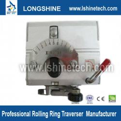
Stepless AdjustmentThe take-up reel transfers a certan speed to the polished shaft.Without changing the roatating speed of the shaft though move the indicator on the scale dial,adjust the traverse drive’s speed of reciprocating motion on the shaft,range from 0 to the maximum pitch setting.
Instantaneous ReversalWith no need to change the shaft speed of rotation,when rhe reversal trigger roller contacts the end stop,the travel direction of the traverse drive will be pivoter to its mirror direction with reversal time of not more than I second.
High Traverse SpeedThe traverse drive speed of linear motion on the shaft can be up to 0.4m/sec.max..,and the applicable speed is Usually 0.3m/sec. So it can meet the requirement of some situations for high traverse speed and very frequent reversal.
Release AssemblyThe traverse drive features the release system..It allows the rolling rings to disengage from the shaft without the shutdown and so can be manually moved at any position on the shaft.It can traverse from the end part.
Installation instruction
It is important to prepare the polished shaft ,the guide bar,the end stop leda screw,the end stops,etc.according to the installation dimensions of relative types and the technical requirements of equipment,as the figure shows.
Polished ShaftSurface hardness:HRC50-60;Tolerance on diameter:h6;True running tolerance:<0.1mm/m;Length:not larger than 20-30 times of the diameter of the shaft;Leading end chamfer:2x30°.
Ratio of take-up reel and the shaftin general,the shaft speed should be smaller than the take-up reel speed so that the shaft and traverse drive lives could be increased.It is recommerded that the rotation ratio of the shaft over the take-up reel be1:1-1:5,with lower ratio for thicker wires and higher ratio for thinner wires,and the scale indication not being less than1.
Direction of Shaft Rotationthe rotation direction of the shaft transmitted by the take-up reel may be eitter positive or negative,however,there is difference regarding the installation positons of the reversal arm,or otherwise the direction could not be switched.When facing the scale dial, downward rotation is defined as positive.The reversal may be realized only when the trigger roller is installed backward.The shaft rotation is presetted and installed as in positive direction at the factory.
The following is the C type detail
Advantages andInstallation instruction
The maintenance is mainly performed for three purposes:achieving instantaneous reversal,constant reciprocating pitch and adequate side thrust.
Reversal PointsTo keep symmetrical the angles of the fixed arm and the movable arm ,torsion springs shall be kept preese between the fixed and movable springs.The spring shall be replaced in case of inadequate pressure.
Traverse ThrusrThe thrust is mainly dependent on the adjustable nuts and the pressure of disk spring. On the bottom of the traverse housing there is one or two nuts that can be adjusted. When adjusting the pressure,attertions shall be paid that certain clearance be allowed between the Polished Shaft and the sealing covers on adjusted as too tight a thrust may prevent the Polished Shaft fromreversing. So in case of the traverse thrust required is met,adequate thrust will incease the lives of the Polished Shaft and the traverse housing.
Pitch Adjustmentthe travers housing might travel asymmetrically on the shaft,because of the difference of positive and negative angles of the eccentric shaft and the housing.The asymmentry problem can be solved by loosing the two set screws on both sides of the scale dial arld a slight left or right tuning for adjusting the symmetrical position of eccentric shaft and housing.
Maintenanceit is necessarry to keep a film of lubriction of the shaft and the reversal mechanism to promote the operational lifte of the shaft and the drive assembly.
How it works
The end stop assemblies (C) are mounted on two shafts called guide rails (D). The front most shaft is fitted with the end stop ratchet lever (E). A cam (G), affixed to the rolling ring drive (A), is positioned so the ratchet lever is actuated each time the drive passes by. When the lever is actuated, the front shaft rotates relative to an adjustable value, which is preset using the control knob (F). As the shaft turns, it bears against the bearings (H) mounted on the end stop assemblies. The bearings are pressed against the smooth shaft and function like a screw to move the end stop assemblies apart. As the end stops - which trigger the reversal mechanism (B) -- move apart, the required increase in stroke length is achieved. When the spool is filled, the assembly is easily reset by hand.
| Packaging Detail:We can according to customer's requirements |
| Delivery Detail:It depends on customer's QTY |
Related Product for RG Linear drive linear guide rails
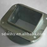
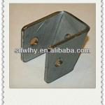
products made from sheet metal
products made from sheet metal,Sheet metal cutting&bending,Stamped Sheet metal. We make quality moulds , quality parts.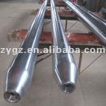
AISI H11 Mandrel bar for Pilger mill
1.Dia 80 to 450mm Length 2500 to 17500mm2. Material AISI H13, X38CrMoV5-1(1.2343), X40CrMoV5-1(1.2344),28NiCrMoV10(1.2740)
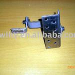
Custom -built metal stamping part
Custom -built metal stamping part,Sheet metal stamping part,metal stamping bending part.good quality ,competitive price
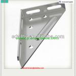
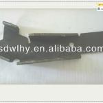
Sheet metal stamping bending part
Sheet metal stamping bending partKeywords:Bending part,Stamping bending part,Sheet metal stamping
Material:Carbon steel .
Precision sheet metal stamping part
PRESCISION SHEET METAL STAMPING PARTgood quality ,competitive price ,good service make good return.
Precision Metal stamping bending part
Metal stamping part could be used in many lines of industry .our parts have good quality ,competive price and big market.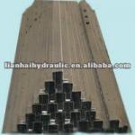
bending welding stainless steel
bending welding stainless steel1.30years experience
2. ISO and CE certification
3. OEM manufacture
precise steel stamping part
Stamping Partsa. material: steel , stainless steel, aluminum
b .treatment : zinc plating, powder coating, electroph

U Type Radiant Tube
U type Radiant tube:Material:ZGCr25Ni20;ZGCr25Ni35Nb;ZGCr28Ni48W5,or at customers request.
metal stamping product
Stamping Partsa. material: steel , stainless steel, aluminum steel
b .treatment:zinc plated, powder coating,other finished
Small batch production of various products High precision Press components
OEM productsWe manufacture products using methods and materials
that meet the demands of the client.

High precision press metal components small batch production of various products
OEM productsWe manufacture products using methods and materials
that meet the demands of the client.