
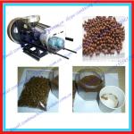
MINI PELLET MILL
| Condition:New | Place of Origin:Izmir Turkey | Brand Name:KOCAMAZ | Model Number:MINI PELLET MILL |
| Type:Feed Pellet Machine | Voltage:380 | Power(W):22 KW | Dimension(L*W*H):TOTAL 250 M2 |
| Weight:7500 kg | Certification:ISO 9000, CE | Warranty:1 YEAR | After-sales Service Provided:Engineers available to service machinery overseas |
| COLOR:Blue - Grey | POWER OF MILL:30 hp - 22 kw |
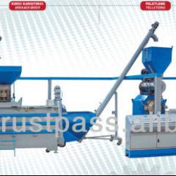

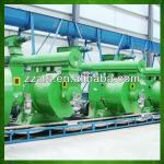
NEW SYSTEM POWDER and PELLET FEED PLANT
- The purpose of the New System of Dust Feed and Pelleted Feed Factory is to enable the stock owners to produce their customized pelletized feeds. Thanks to the process, the stockfarmer will be able to determine the material that will be included in the feed and the dependency for stockfeeding will be minimized.
- Both powder and pelletized feeds can be produced in the facility thanks to the1250-1750 kg/hourproduction capacity of the facility.
- All the equipment in the high capacity feeding facility are included in the system as their capacities adjusted in accordance with the system requirements.
- All of the machinery and technical equipment within the facility can be added or removed according to the customer demands. For instance, a firm manufacturing powder feeds may begin to purchase the system components beginning from the pelletizing machine.
The Areas of Implementation for the System
- The Feeds and the Milk of the Cattle and the Small Cattle
- The Poultry Feeds
- The Pelletizing of Prina(Olive-Pornace)
- Is Suitable for All of the Cereal Groups
The Set Up Requirements of the System
- A 250 m2 area with 5 m height,
- A 105 KW transformer station,
- A team of 3-4 people to conduct the operation are sufficient.
FOR WATCHING WHILE WORKING PLEASE GO TO THIS LINK:
http://kocamaz.com.tr/en/product/pellet-feed-factory
A) The Raw Material Input
It is composed of the raw material input bunker and helix. The purpose of this system is to convey the raw material, which is placed onto the ground by spilling, to the two horizontal U-type helices which will transfer it to the silos. Two directions are available at the exit edge of the helix and the desired direction can be implemented via the use of the pneumatic lid. The raw material carrying capacity of the helix is 4.5 tones/hour and its length is 6.5 meters.
B) The Silo Group
There are 6 silos present in our current system. There are 2 helices with 3 exits over the silos. Which raw material will be transferred to which of the silos is determined in the main panel and the filling process to the desired silo is realized thanks the implementation of the pneumatic valves. The standard silo size is 1000x1000x2500 mm and the silos are manufactured from 3mm of sheet iron. The approximate silo size is 2.3 m³. The silo dimensions and the number of the silos included in the system can be customized according to the customer demands.
The Silo Operating Principles : Compound feed up to 500 kg can be prepared at once in the system following the input of different raw materials into the silo. The amounts of the cereals that will be used from each silo is entered in the ratio panel and the desired amount of the desired raw material is transferred to the system via the lower helices.
C) The Dosage Group
The dosage bunker has the 1240 x 1240 x 1100mm size and is manufactured from 3 mm of sheet iron. It is mounted onto the 4 llama type load cells each of which are of 500 kg capacity over the dosage weighing bunker.
The dosage weigh-bridge has a pneumatic emptying lid. The materials are sent in to the dosage weigh bridge in accordance with the desired ratios. Then the pneumatic lid empties the product into the weighing bridge bunker in one lower lever. When the product in the weighing bridge is emptied the pneumatic lid is closed and the ratio adjustment process is initiated n the upper level for another cycle, whereas the mixture that has already arrived from the upper level is emptied into the bunker of the grinding unit via the dosaging helice.
D) The Breaker & Mixer Group
The mills are manufactured from 2 units being the grinding unit and the mixing unit. The aggrieving capacity is between 1750 to 2000 kg per hour.
The Grinding Unit:The 6 mm sieve has 4 tones of grinding capacity. The grinding motor works with 22 KW in 3000 d/d. The grinding unit is surrounded by a 360° sieve. The feed is processed into the system from the middle (The system operates with a vertical grinding mill). The system is manufactured with the latest technology and provides a more homogeneous grinding process in comparison with the other systems and operates without as much noise. The thickness of the grinded feed is adjusted via the implementation of sieves with larger or thinner holes. The second component of the system is the mixing unit.
The Mixing Unit: The mixer has a motor of 7.5 KW power with a 1800 liter volume. The mixer is composed of two helices which are intertwined in each other and are located as right-oriented and left-oriented. The initiation is maintained with a soft-start initiation in order to provide ease in the start up. When materials such as minerals, salts, etc. are added into the feed following the grinding procedure, the scientifically adjusted feed is achieved. In accordance with the demand of the user, the final product is either emptied into the packaging unit for being packaged as powder feed into sacks or is transferred into the helix of the pelletizing bunker to become pelletized.
The Weigher Unit:The weigher unit is used to obtain the products to be packed at standard weights once the feed had been transferred from the sack filler unit through a packed. The weigher unit with digital indicator is programmable through the combined keys.
D) The Breaker & Mixer Group Technical Features
| TECHNICAL FEATURES | KT 1000K |
| BREAKING & MIXING CAPACITY | 1.750 - 2.000 kg/h |
| BREAKING CAPACITY | 1.600 - 5.500 kg/h |
| MIXING TIME | 5 min |
| MIXING CAPACITY | 1.800 lt |
| SACK FILL TIME | 20 s |
| BREAKING MOTOR POWER | 25 Hp, 380 V |
| MIXING MOTOR POWER | 10 Hp, 380 V |
| SACK FILL MOTOR POWER | 3 Hp, 380 V |
| WEIGHT | 1545 kg |
| DIMENSIONS ( W x L x H) | 337 x 150 x 248 cm |
| NUMBER OF BLADES | 72 |
| WEIGHER UNIT | ||
| WEIGHING CAPACITY | 100 kg | |
| BOARD WEIGHING | Digital - Programmable | |
E) The Pelletizing Group
Pellet Pressing Feeding Helix and Bunker:The grinded and mixed product is transferred into the pellet pressing bunker via the helix. The overflowing of the material from the bunker is prevented via 2 level adjustment sensors.
The Conditioner Feeding Helix:The product which is transferred into the pellet pressing bunker is then passed through the conditioner feeding helix that operates to feed the pellet pressing machine on a regular basis. The feeding helix is controlled with the pace adjustment equipment and is a Ø160 U helix made of stainless iron sheet of 3 mm thick. It consists of double twisted stainless sheets of helix and has 1400 mm of length approximately.
The Conditioner :The genuine purpose of the conditioner unit is to provide the homogeneous addition of the liquidified or the steam material that will be added to the product during pelletizing. It has Ø340x1400mm size and is made from stainless iron sheet of 3 mm thickness and has a mixing unit with a puddle. The steam and the molass entries are adjuncted into the system. The steam is provided into the system via an electrical boiler.
The Boiler :The boiler has 80 kg of steam production capacity. It contains a 60 KW power electrical resistance and an automatic pump with a 4 level switch. It contains a high pressure safety system and an audible alarm system. The steam inside the water is separated thanks to the boiler and is transferred as dry steam in order to be fused with the feed in conditioner. The ratio of the steam inside is adjusted according to the ratio of the feed provided inside.
THE PELLET PRESSING ( 240 P):
The pellet pressing engine has 22 KW power and 940 d/d. the engine belt is moved by a pulley. The hourly capacity of the engine differs between1250 to 1750 kgand is changed according to the diameter of the pellet disc, the ratio of the cereals contained in the feed and the type of the raw material used.
Feeds up to 4-5-6 mm size can be obtained with the pellet pressing machine. A separate disc is required to obtain every diameter. The length of the pelletized feed can be adjusted via the knives mounted on the lid. The pelletizing process is maintained via the manually adjusted double roll system.
The disc X46Cr13 is manufactured from specialized raw material. The disc and the rolls used in the system are specially manufactured for our company in the Netherlands.
A thermal switch is present in the electrical panel to protect the engine against overloading during the packaging. By taking the situations that the thermal switch will not function into account, a safety pin is situated in addition as the mechanical precaution.
The pelletized product comes out of the pelletizing machine approximately in 50 to 60 degrees Celcius temperature. When the product is packaged directly, it will not only disintegrate but will also burn inside because of the excess heat it contains. In order to prevent these undesired consequences, a cooling process is required if the pelletized product will not be cooled in its natural medium.
F) The Cooling Group
The product which is pelletized byThe Feeding Conveyor Z, is transferred to the cooling unit for the cooling process. The 450 bucket is manufactured from 3 mm of iron sheet and has the horizontal size of 4330 mm and is in 3450 mm height.
The Air Locksare located in the entrance of the cooling unit and at the cyclone exit. They both provide the regular flow of the materials to the cooler and also prevent the air emission from the upper side, which is important since the cooling process is facilitated via aspiration.
The Cooling Cabinmaintains the cooling of the hot pelletized product that has arrived. It is manufactured in 1350 x 1350 x 1800 mm size from 3 mm of iron sheet. It has 3 tones of cooling capacity per hour. The system with reverse air flow movement that is commanded by a three grid containing reductor with brakes is used for the cooling process. The air in the medium is absorbed from the bottom of the system to the top and when the air passes over the pellets it also removes the hot air over them. Thus the pellets are cooled.
The CycloneandThe Fanare components of the cooling unit. A fan absorbs the thin dust coming from the cooled pellets and gathers them in the cyclone to prevent them to be discarded from the chimney. The fan has a 5 m3 capacity. The heavy dust particles are accumulated by passing through the cyclone to the air lock. This product can be reentered into the pelletizing machine for repelletization.
The pellet that had been cooled via the sensors over the cooling group is fallen onto the pellet sieve in one lower group in order to become sifted. The dust ratio of the pellet is about 2 to 3 %.
The Vibrating Sieveseparates the dust of the pelletized feed. It is manufactured from 3 mm of iron sheet in 610 x 1000 mm size. The hole diameter of the sieve may change according to the pellet diameter. The dust of any kind of pellet can be removed and a special chassis system is adjuncted into the system to minimize the vibration effect.
G) The Packaging Group
The end product is transferred to the packaging bunker viaThe Bagging Conveyor Z. The 450 m3 bucket is produce from 3 mm of iron sheet. Its horizontal size is 4330 mm and its vertical size is 3450 mm.
The Bagging Unitis a sensitive weighing machinery for the packaging of the feed in bags of 25 kg or 50 kg size. It operates with a load cell and has pneumatic control. The machinery can process fast and sensitive weighing and has sudden product cutting switch. The machine can provide sensitive filling process up to – , + 50 grams.
The Sewing Belt, is the band onto which the sacks fall onto following the automatic completion of the weighing process. It is 3000 mm in length and 400 mm in width and has the special bag tilting apparatus.
The mouths of the sacks are automatically stitched via TheSewing Machineand thus the operation is completed.
| Packaging Detail:IT DEPENDS ON REQUESTED EQUIPMENTS |
| Delivery Detail:30 DAYS |
Related Product for MINI PELLET MILL
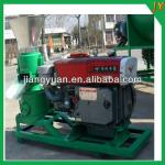
Good quality poultry pellet feed machine with diesel engine
1. small pellet machine2. Suitable for pigs, sheep, chicken, fish and so on.
3. High quality
4.Low consumption
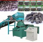
straw briquette machine/biomass pellet making machine/sawdust briquette machine/0086
1.can make diameter:8mm-33mm biomass briquette,2.raw material can be wood ,sawdust .straw and other things .
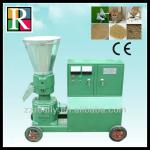
CE approved mini feed pellet machine for pet food for sale
pellet machine for sale1.Various types and use
2.High efficient
3.Pro-environment
4.CE and ISO
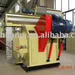
Simple maintenance ring die pelletizer mill machine
Ring die pelletizer mill1,High molding rate,
2,good-looking appearance,
3,Good strength,
4,Small footprint,
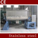
New Stainless Steel Ribbon Mixer Machine For Mixing Powder With CE
1, ribbon mixer machine2,Pneumatic butterfly valve discharge
3, big capacity
4, CE certification
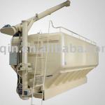
BQSZC-10T Bulk Feed Transportation Tank
1.Discharge height:7 m2.Capacity:10 ton, 17 CBM
3.2 or 3 compartments
4.Combine transport and discharge
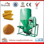
vertical poultry feed crushing and mixing machine meet your quality with CE confirmeded
poultry feed crushing and mixing machine1.CE,SGS and BV confirmed
2.High capacity of 500-2000kg/h
3.2years warranty
Electric motor or diesel engine maize grinding hammer mill for sale
Electric motor or diesel engine maize grinding hammer mill for sale1.adjustable power
2.200-1500kg/h
3.widely use
feed pellet mill
1,output :3-7T/H2,main power:30x2kw
3,feed power:0.75kw
4,additive power:2.2kw
5, net weight :2400kg
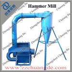
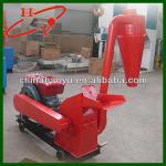
Best Quality Wood Pellet Hammer Mill/Hammer Mill Crusher with Best Price
Wood Pellet Hammer Mill1.Firm Structure
2.Easy Operation and Maintain
3.CE Approved
4.OEM Service
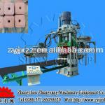
Hydraulic press mineral salt block machine for animal
mineral salt block machine1.high press
2.PLC Controll
3..high output,low energy consumption
3.Safety
Competitive price floating pellet making machine for fish/pet food machine/008615514529363
floating fish pellet making machine1Suit for water live animal or pet etc
2 feed pellet can float in the water
3.high qual