
INSULATED CONDUCTOR RAIL SYSTEMS U12
| Place of Origin:Jiangsu China (Mainland) | Brand Name:Komay | Model Number:KM-U | color:green |
| length:4m,6m | Main material:copper | Implemerotation of standards:JB6391-1992 | Installation place:Indoor |
| Dielectr strength:3000V/1min | Protection grade:IP23 | Max. Voltage:AC660V or DV 1000V | Operating speed:V≤600m/min |
| Pollution level:4 |
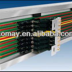

General
The shrod which envelopes the various conductors is an excellent insulator.
therefore our unipole insulated conductors gurantee utmost safety in operation.
Any number of conductors can be installed side by side at minmum space requirement.
Standard rail sections are 6m long ,shorter sections are available.
The ground conductor is identified by international colour coding.
For obvious safety reasons phase and ground collectors are not interchangeable.
Approved and listed by:CCC,CEand IS9001.
Hangers
Bolted,snap-in and guarter turn typr hangers are available. Standard support distance for U12 is 600mm, in curves 300mm.
Joints
Snap-in joint splices provide mechanical end electrical continuity. They include insulated protection covers. Expansion joint sections are only required incase of expansion joints in the monorail track.
Feed terminals
Joint assembly and mid-rail assembly feeds are available . Furthermore transfer guides and isolating assemblies allow for space connetors.
Transfer guides
Transfer guides serve as an end protection of system runs and accomplish amooth smooth collector transfer in case of switches,drop sections etc. They can be supplied with or without feed clip.
Isolating assemblies
Conductor isolating assemblies are available for sectionalizing control circuits, maintenance bays etc. They can be supplied with or without feed clip.
Curves
U12 can be uesd for horizontal or vertical curves. A special curve tool forindividual fiele preparation is available.
Collectors
The current collector are made of reinforced polyamide and stainless steelparts. These spring loaded units provide positive contanct with the conductor bars and have double pick-up brushes.
U12 conductor
Engineering date of shroud
| Electrical properties Specific resistance Surfance resistance Leakage resistance | standard shroud color green 30-40kv/mm 5×10¹⁵Ohm × cm 1013Ohm CTI600-1.1 | high temp.shroud 45kv/mm 5 ×10¹⁷Ohm × cm 1015Ohm CTI600-1.1 |
| Mechanical properties: Flexible strength: Tensile strength: | 75N/mm2±10% 50N/mm2±10% | 95N/mm2±10% 50N/mm2±10% |
| Working Temperature Flame test proof Resistance to chemicals: | -30°c~+55°c -30°c~+110°c no flaming particles, self-extinguishing Hydrochloric acid concentr. gasoline,mineral oil, grease caustic soda solution 25% and 50%, sulphuric acid to 50% | |
conductor code
U=unipole insulated conductor
12=shroud size
25=conductor cross sectional area(mm2)
conductor spacing
on compact hangers 14mm or variabloe.
Curves
min.R=0.4mm
Length
6m is standard length, length are available.
Support spacing
for straigth runs 0.6m, for curves 0.3m
Application
indoor use only. See "Engineering date of shroud"
| Type | U12/25 |
| Weight(kg/m) | 0.267 |
| Standard shroud,color green | |
| Cat.-No.phase Cat.-No.ground | 668116* 668216* |
| High temperature shroud | |
| Cat.-No.phase Cat.-No.ground | 668316* 668416 |
Fill-in last number(1,2,3,4,5,6m suffix) in accordance to bars required.
Engineering date
| conductor rail type | Cross sectional area | Leakage distanc of covers | max.voltage | Continuous ampere capacity | resistance |
| U12/25C** | 25 | 30 | 600 | 100 | 0.745 |
| U12/25F** | 25 | 30 | 600 | 40 | 5.415 |
| U12/25E** | 25 | 30 | 600 | 10 | 31.56 |
**C=copper coductor F=galvanize E= stainless steel conductor
Selection of Conductors
in accordance to ampere load environmetal conditions
for power, control-and data-transmision.
for non-non-corrosivent.
for control and data-transmission in corrosive atmospheres
Compact double collector
two-away converying
for conductor spacing of 14mm
1 Plug terminal 20A
2Plug terminal 2×20A
Swivel:±15mm lift:±15mm
contact pressure 3.5N per brush
ground at NO.4, other position on request.
| Type | poles | a | b | c | weight(kg) | Cat.NO. | |
| JDS2-1/40-1 | 1 | 80 | 118 | - | 0.165 | 663201 | |
| JDS2-2/40-2 | 2 | 80 | 118 | - | 0.245 | 663202 | |
| JDS2-3/40-3 | 3 | 80 | 118 | - | 0.325 | 663203 | |
| JDS2-4/40-4 | 4 | 80 | 118 | - | 0.405 | 663204 | |
| JDS2-5/40-5 | 5 | 80 | 118 | - | 0.495 | 663205 | |
| JDS2-6/40-6 | 6 | 80 | 118 | - | 0.575 | 663206 | |
| JDS2-7/40-7 | 7 | 80 | 118 | 53 | 0.735 | 663207 | |
| JDS2-8/40-8 | 8 | 80 | 118 | 53 | 0.825 | 663208 | |
| JDS2-9/40-9 | 9 | 80 | 146 | 53 | 0.925 | 663209 | |
| JDS2-10/40-10 | 10 | 80 | 146 | 53 | 1.005 | 663210 | |
| JDS2-11/40-11 | 11 | 120 | 174 | 80 | 1.125 | 663211 | |
| JDS2-12/40-12 | 12 | 120 | 174 | 80 | 1.205 | 663212 |
Compact double collector
for conductor spacing of 14mm
1Plug terminal 40A
Swivel: ±15mm lift:±15mm
contact pressure 3.5N per brush
ground at NO.4, other position on request.
| Type | poles | a | b | c | weight(kg) | Cat.NO. | |
| JDS1-1 | 1 | 80 | 118 | - | 0.140 | 663101 | |
| JDS1-2 | 2 | 80 | 118 | - | 0.205 | 663102 | |
| JDS1-3 | 3 | 80 | 118 | - | 0.270 | 663103 | |
| JDS1-4 | 4 | 80 | 118 | - | 0.335 | 663104 | |
| JDS1-5 | 5 | 80 | 118 | - | 0.425 | 663105 | |
| JDS1-6 | 6 | 80 | 118 | - | 0.490 | 663106 | |
| JDS1-7 | 7 | 80 | 118 | 53 | 0.625 | 663107 | |
| JDS1-8 | 8 | 80 | 118 | 53 | 0.690 | 663108 | |
| JDS1-9 | 9 | 80 | 146 | 53 | 0.786 | 663109 | |
| JDS1-10 | 10 | 80 | 146 | 53 | 0.850 | 663110 | |
| JDS1-11 | 11 | 120 | 174 | 80 | 0.955 | 663111 | |
| JDS1-12 | 12 | 120 | 174 | 80 | 1.020 | 663112 |
JDSL-are used for I-beams, Fill-in last number(1-12)in accordance to bars required.
Special features
High safety level with integrated finger protected insulation
Easy and exact mounting with multiple hangar clamps and bajonett conector technology
Unlimited amount of pole design for complex
Easy installation in courves with bending option
Flexible power feed options
Main applications
EMS Eleotro monorail systems
Stretcher / Packing equipment
Amusements rights
Ring application or slip rings
Stage equipment
Sorter
Maintenance
--After installation,Make sure that the sliding hangers are straight (in a perpendicular position) after nuts have been tightened to guarantee free sliding of the powerail.The powerail must be installed exactly straight and parallel to the machinery track.
--Before running the powerail,Check the system for esay running of the current collector trolleys,i.e.there may be no resistance by an excessively narrow slot or pull by the connecting cable.
--Every 3 up to max.12 months,-depending on the frequency of operation and travel distance-,check the carbon brushes and mechanical componets for wear and replace them if necessary.
| Packaging Detail:plywood box or According to customer requirements |
| Delivery Detail:2-4 weeks |
Related Product for INSULATED CONDUCTOR RAIL SYSTEMS U12
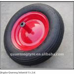
Wheelbarrow rubber wheel
1.Size:3.50-82.Origin place: Qingdao,Jiaonan
3.Good quality and competitive price
4.Various Sizes available
5.OEM accpeted

PU wheel for hand truck
PU wheel1.Flat Free + Puncture Free + Supper Light + No Marking
2.high quality
3.more size
4.competitive price

solid rubber wheel
solid rubber wheel1.Size:114x30mm
2.bore diameter:10.8mm
3.wheel base: 31.5mm

Wheelbarrow 3.25/3.00-8 Tyres and Tubes
Wheelbarrow 3.25/3.00-8 Tyres and Inner Tubes
substitute for steel wire / Kevlar rope
subustitute for steel wire / Kevlar rope*high tensile strength
*lighter than wire
*high flex life
*excellent insulation
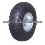
10 inch Pneumatic Rubber Wheel PR1800
Pneumatic Rubber Wheel for wheel barrowPR1800
Size:10*3.50-4
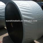
Rubber conveyor belt
Rubber conveyor belt1.EP200,EP250,EP300,330PIW,440PIW
2.8MPA,10MPA,15MPA,18MPA
3.resistant to abrasion,impact and tear

Solid rubber wheel SR1310
13"x3" solid rubber wheel for wheel barrowRubber solid wheel with metal rim
Metal rim with ball bearing
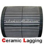
pulley ceramic lagging
ceramic pulley lagging1.Highly improve coefficient of fraction
2.High abrasion resistant
3.Long working life:5~8years

forklift parts Cylinder Assy,Clutch Release
we supply full range forklift parts of:TOYOTA,MITSUBISHI,KOMATSU,NISSAN,TCM,HYSTER,LINDE,DOOSAN,HELI,HANGCA.....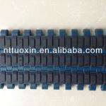
SuperGrip 1005 with rubber on top modular belt
Type: SG1005Material: PP
Belt pitch: 25.4mm
Open area: 0%
Assembling method: Connected with rods
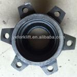
HANGCHA Forklift spare parts Hub
(1) Brand: Hangcha(2) Cheap price, good quality and better service
(3) OEM