
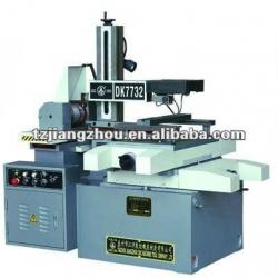
DK7732 CNC Wire Cutting Machine
| Condition:New | CNC or Not:CNC | Place of Origin:Jiangsu China (Mainland) | Brand Name:JZ |
| Model Number:DK7732 |

| Parameters/type | DK7732 |
| worktable travel(mm) | 320×400 |
| max. workpiece cutting thickness(mm) | 400 |
| worktable displacement(mm) | 4 |
| machining precision(cutting octagon)(mm) | 0.015 |
| max. cutting speed(mm²/min) | 100 |
| max. cutting taper(optional) | 6°-30° |
| worktable's max. load(kg) | 300 |
| wire electrode diameter(mm) | Φ0.12 - Φ0.18 |
| wire storage cylinder dimensions(mm) | 150×200 |
| max. wire length(mm) | 320 |
| equivalent pulse(mm) | 0.001 |
| stepped motor | 90BF006 |
| wire storage cylinder motor | AC:YS7124 370w 1400rpm DC:110SYT 185w 1500rpm |
| operation liquid pump | AB25 90W 25L/min |
| outline dimensions(mm) | 1550×1280×1400 |
| machine weight(kg) | 1400 |
| total power | 2kW AC380V/220V 50Hz |
The high-end machine adopts precise ball screw linear guide track.
High column matches electric lift to adjust the gap of guide wheel and large swing taper machine matches electrode wire wire expansion mechanism.
We also produce semi-closed environmental-protection machine.
The diameter range of molybdenum wire is 0.12mm-Φ0.18mm (moly wire diameter over than Φ0.18mm should be customized).
The maximum working speed is over 100mm ²/min and the best surface roughness is less than Ra2.5 μm.
Machine tool structural summary:
1 Bed:
The machine tool is the cast iron box.
Its upper part takes the tray shape.
On the bed, there are worktable, wire drive device, wire support and floodlight.
2 Coordinate worktable:
The coordinate worktable is composed of the worktable, lower trailing bar, precision roller (slide) screw rod pair and the gearbox.
Use roller track structure for the horizontal and lengthwise movements of the trailing bar.
The worktable movement is realized through the stepped motor, the deceleration gear set and the screw rod pair.
The screw rod nut is pre-tightened axially so as to make the gap between the screw rod and the nut close to zero.
There are 2 T-shaped grooves on the worktable for fixing the clamps.
3 Wire drive device:
The wire drive device is composed of the wire storage cylinder, trailing bar, gear set, slide screw rod pair, bearing house and base.
The wire drive device realizes the high-speed to-and-fro movement of the wire electrode.
The wire storage cylinder is reliably insulated.
The motor drives the wire storage cylinder rotation through the flexible shaft coupling.
The shift gear set drives the screw rod, which drives the trailing bar to discharge the wire so as to realize the circulative use of the wire electrode.
Use a group of travel switches to control the frequent reversion of the trailing bar of the wire storage cylinder.
Adjust the distance between the shift forks according to the wire discharging width of the wire storage cylinder.
Leave 3mm wide wire electrode as the non-working section at each end.
If the wire electrode has diameter more than 0.18 mm, order separately change gear set.
During the operation of the machine tool, be sure not to move the waterproof cover on the side of the wire storage cylinder.
4 Wire support:
The wire support is used to support the wire electrode.
It is composed of the pillar, upper arm, lower arm, conductive block and the guide wheel.
The upper arm can move upward and downward so as to adjust the span between the upper and lower guide wheels and to suit the machining of the work pieces with different thickness.
The guide wheel and the conductive block are encased into the wire support and insulated from the upper and lower arms.
The wire discharge wheel (wire blocking rod) at the back ends of the upper and lower arms can avoid wire overlapping.
The water valve is installed at the lower part of the column.
The two knobs on the panel are used to adjust the operation liquid flow rate from the upper and lower nozzles.
The taper head (coordinate cross trailing rod) is installed at the top of the upper arm so as to realize the movements of the guide wheel in U and V axis, to form some angle between the wire electrode and the worktable and to realize the tapered cutting.
The machine tools with maximum cutting taper 30° use the wabble mechanism to realize the simultaneous deflexion of the upper and lower guide wheels so as to ensure the big taper machining precision.
5 Operation liquid system:
It is used to provide the operation medium, that is, the operation liquid with certain insulation function.
At the same time, it can cool down the work piece and the wire electrode.
The water pump pumps the operation liquid for wire cutting to the machining area.
This is in favor of the sparkle discharge and the scrap discharge.
The operation liquid flows back to the operation liquid box through the water pipe and it is recycled after filtration.
The residue settles in the waste box.
The operation liquid box shall be cleared up regularly and the operation liquid shall be replaced timely.
Use the tapped water or diluted water to prepare the operation liquid according to the mixture ratio.
Accessories:
a) Clamps
b) Wire tightening device
c) Wire installation support
d) Verticality meter
e) Crank
f) Guide wheel dismantling tool
g) Special accessories for big taper machine tools
h) Straight-line nozzles
DK7732 CNC Wire Cutting Machine
| Packaging Detail:wooden containerDK7732 packing: 1.75*1.25*1.95m net weight: 1078kg gross weight: 1200kg |
| Delivery Detail:within one month |
Related Product for DK7732 CNC Wire Cutting Machine
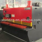
QC11Y Hydraulic Guilotine Shearing Machine
1.Steel Welded Frame2.Hydraulic,Nitrogen back cylinder
3.Shear stroke and angle adjustable
4.Delem DAC-360 control system
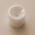
C102-1 Charmille EDM Wear Parts Diamond Wire guide
C102-1 Charmille EDM Diamond Wire guide1.Material:Diamond and Ceramic
2.Size:0.20mm,0.25mm,0.30mm
3.For Robofil series
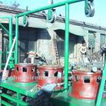
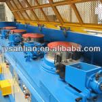
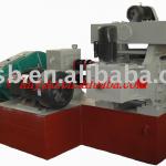
pulley type continuous wire drawing machine
1w1-4/550 11kw,10ton/24hDrum diameter:550mm
Inlet/outlet wire dia:6.5-4.0-2mm
Weight of single block: 2000kg
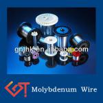
Molybdenum Wire for EDM/ CNC wire cutting machine 0.`4mm
0.14mm edm/cnc Molybdenum wire1.Density:10.20g/cm3
2.Purity: Mo99.95%
3.Standard:GB/T4182-2003
4.Demension: 0.05-5.0mm
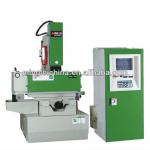
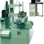
High precision EDM machine ZNC-320
1. High precision EDM machine ZNC-3202. High precision, high efficiency
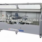
Aluminum Curtain Wall notching Saw / notching Saw For Curtain Wall Machine
1.Notching saw for aluminum profile,curtain wall machinery2.Branch office In India
3.CE,ISO9001:2000
dry wire drawing machine LZ 6/550
1. dry wire drawing machine LZ 6/5502. have gotten ISO 9001:2008 standard certification
HOT SELL! metal cutting machine FOR REBAR
Metal cutting machine for rebar1)diameter: 4mm to 12mm
2)fast speed
3)precise machines
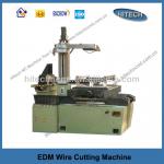
DK7740AZ CNC edm wire cutting machine
CNC edm wire cutting Machine1.Worktable size (mm)720x460
2.Table travel (mm) 500x400
3.Overall dimensions (mm)1680x1390x1540
DK7732 fast cut cnc wire cutting machine
fast cut cnc wire cutting machineaccurate, easy operate
linear guide rail
high precision,heavy, low noise
TM/ ISO9001:20
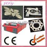
Stainless steel cutting cnc plasma machine
steel cutting cnc plasma machine1.Low price , stable quality
2.high precision, no residua
3.fast delivery
4.CE,big factory
HXE-9DST intermediate copper wire drawing machine with continuous annealer
9 dies intermediate wire drawing machine with continuous annealerinlet size:2.6-3.5mm outlet size:1.2-2.76mm
speed:1000m