
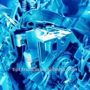
Crosshead bearing wear monitoring system
| Condition:New | Place of Origin:Germany | Brand Name:Hornel BDMS/BTMS | Model Number:BDMS |
| Voltage:24VDC/115-230VAC | Power(W):25W | Certification:GL | Warranty:12 months T and C apply |
| After-sales Service Provided:Engineers available to service machinery overseas | Bearing distance monitor:Two decimal place of mm distance, Degree Celsius |

Specifications
Bearing Distance Measuring System is to monitor the condition of the crosshead bearings of two-stroke engines failure prediction
BDMS / BTMS for two-stroke diesel engines
System overview:
The system consists of the following components:
1. BTMS/BDMS indication and master unit
2. Connection boxes.
3. Transfer box.
4. Sensors type IW000184 with brackets.
5. Water-in-oil sensor type FRG00032
1. Indication units
The indication unit is available in two executions, one built into special field housing for direct installation in engine room, and one in a version to be mounted in a switchboard panel or engine control console with IP68 from the front and IP20 from the backside.
The field housing is equipped with EMC cable glands allowing the connection of the serial link bus bable, the 24VDC power supply, the connection of the RS232 to ship's or engine's computer as well as the relay outputs.
1.2 Indication unit display for BDMS + water-in-oil sensor only
The BDMS indication shows the readings of one comparment at a time, the bearing wear situation + splash oil temperature delivered by the distance sensors type IW000184.
The display has two bar graphs, each on one side of the screen, two temperature indicators and an indication of the compartment it is on at that moment.
By optical buttons left/right of the compartment number, it is possible to select another compartment.
The two bar graphs indicating the momentary situation of the wear status detected by the sensors type IW000184. The temperature indicators delivering the splash oil temperature in the vicinity of the sensors.
The lower LED row of the display indicates how many distance sensors are installed and the state of the distance sensors (whether in the alarm or woring or failure condition). If a water-in-oil sensor is installed, this is indicated in the end of the LED row.
1.3 Indication unit for BDMS including optional main bearing sensors.
Tis display indicates also the temperature of the main bearing besides those under 1.2 described above. Main bearing sensors type TGL00921 visible under MB-Temp A + MB-Temp B. The lower LED row can indicate max. of 14 compartments, but indicated by lighted LED's are the amount of sensors installed only; last two indicating no alarm on water-in-oil sensor present.
1.4 Indication unit for main bearing sensors type TGL 00921 only.
1.5 Indicating unit for all possible sensors mounted inside the engine.
This display cersion is needed if all possible sensors (distance, main bearing temperature, temperature switches and water-in-oil sensor) mounted in the engine.
2. Connection boxes.
The connection boxes type GHG02621-3 is needed for the connection of the sensors to deliver the necessary galvanic isolated power received from the transfer box to the sensors and to establish the serial data link from the sensors to the transfer box.
The connection box has no active electronic on the board and allows maximum the connection of 16 sensors. If more than 16 sensor are installed for engines with more than 7 cylinders, in a system a second box must be installed. A green LED on the board indicates the presence of supply voltage. An electronic fuse protects the box as well as the enclosed electronic units in case of a short circuit in one of the sensors.
3. Transfer box
The transfer box delivers the galvanic isolated power supply and receives the data from all units to the system connected to the sensors. The RS232 data are changed in the transfer box to RS422 and transferred to the indication unit.
The open box has space for a larger DC/DC amplifier which will become necessary if all possible sensors are connected to the unit.
Here it is important at the stage of ordering a system what power is available on or close to the engine. Normally 24V DC is present, but on some engines, the 24V DC power available does not allow the connection of the BDMS due to load limitations. In such ase, 115 or 230V
4. Sensors
4.1 Distance sensor type IW000184
The distance sensor type IW000184 with protection class IP67 is a high speed, intelligent sensor measuring the distance in a range of max. 5 mm with a resolution of 0.01 mm. In addition, the splash-oil temperature in the vacinity of the sensor is measured with a tolerance of +/- 2*C.
This sensor has no thread; the fastening in the engine is arranged by clamping in the brackets.
The sensor detects the crosshead within its distance range and calculates the lowest air gap in two decimal places mm. The value is stored in an internal buffer and constantly at every revolution being updated.
4.2 Sensor brackets
The sensor brackets are needed for correct, vibration-free installation of the distance sensors. Two versions are available; for one and two sensors. Both versions are of clamping type to avoid threaded sensors.
The single version brackets are mounted on both sides under the crosshead sliding plate. . To avoid problems after removal of a double bracket with the exact replacement afterwards, the bracket is aligned by two alignment pins of 5mm. To remove the bracket 8mm thread exists.
4.3 Water in oil sensor type FRG00032
This sensor is designed to monitor the amount of water contnet in the Lubricating oil. The measuring principle is based on the capacitive constant or the dielectric properties of the oil, and the change in this property due to water content.
The capacitive constant change is measured by a microprocessor built-in the electronics, which calculates the values for pre-warning and high alarm thresholds. The default values are 0.3 and 0.5 percent of water in oil v/v. This value is transferred to the indication unit via the RS232/RS422 serial link.
4.4 Main bearing temperature sensor type TGL 00921
This sensor is able to measure the temperature of the main bearing. The miniturized flat design allows mounting at the main bearing support close to the bearing shell. The sensor can easily be placed at the support with the help of internal magnets. If the position is correct in place, it must be secured with oil-resistant glue.
The temperature data measured within a tolerance of ± 1.5oC If a bearing should be overheated above the short time tolerable value, the sensor must be replaced.
4.5 Switch type temperature sensor TGL 01621 for big and small end bearings (option)

| Packaging Detail:Carton boxes. |
| Delivery Detail:Approx. 6 weeks |
Related Product for Crosshead bearing wear monitoring system

building cleaning equipment
1/building cleaning equipment2/with CE & ISO 9001:2000
3/can instead of 20 cleaner's work
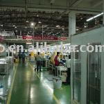
Customized Automatic Microwave Oven Machinery Production line
Factory automation production line, auto assembly and packing, auto dividing and stocking, industry robot, metal sheet auto shap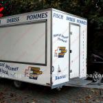
troller
food vending cartsForever be imitated, never be surpassed.
The best selling food cart with high quality,
CE approved.

Plastics granule/caps color processing/sorting machine
1.high sorting accuracy2.LED light
3.real-time monitoring
4.high capacity
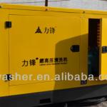
Diesel Engine Drive Water blasting machineLF-76/50 Cleaning machine high pressure washer
500bar 76L/min 75kw packing:in wooden caseplunger diameter:30mm payment: T/t
stroke:70mm

spectra polaris printhead solvent printer/PQ head solvent plotter machine
1, 3.2m print width2, 124 sqm/h high speed
3, Photoprint V10.0 RIP software
4, 2 or 4 polaris head
5, CE certified
Latest Design Hot Selling LED Cutting Peeling Machine
1.LED cutting machine2.Feeding form:Feeding Plane
3.Feet length:3-20mm
4.Processing:150pcs/min
5.Weight:145KG

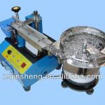
Screw Feeder Electronic Auto-Screwdriving Machine TW-K13
Elecreonic Auto-Screwdriving Machine automatically lock screw machine TW-K131.Small size
2.high qualit
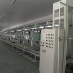
assembly line
Assembly line Assembling Line1.Air purifier assembeing ,testing line
2.Realize automatic
3.Labor&time save
4.Min 1set
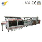
Flexible PCB DES Equipment
It is an automatic des(developing,etching,stripping) line for pcb flexible boards.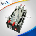
LCD touch screen glass separating machine for Apple Samsung HTC LCD touch screen disassembly Separating
LCD Touch Screen Glass Separating Machine for AppleVoltage:220V/110V
Package Weight:5.8KG
Package Size:20cm*18cm*16cm
Electric Hot Air Oven in Drying Equipment
-Electric Hot Air Oven in Drying Equipment-Strong durability
-Internal heat circulation
-Precise control
-CE,SGS,ISO,CSA