
BI-COMPONENT STAPLE FIBER MACHINE
| Condition:New | Type:Spinning Production Line | Place of Origin:Hunan China (Mainland) | Brand Name:Shaoyang |
| Spinning Method:Rotor Spinning | Automatic:Yes |
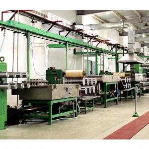

1.General Description
The line is used to produce bi-component fibers like side-by-side type, sheath/core type, adopting chip melting and spinning technology in the main and auxiliary melting systems and the process technology of drawing, feeding and auto can filling controlled by inverters.
The line consists of main production line, auxiliary production line and utilities, mainly including: Main production line for spinning, including Spinning, taking-up and can filling including the HTM system. Auxiliary production line, including packs disassembling, cleaning, assembling, pre-heating, ultrasonic cleaning, spinneret detection and sand preparation, Preparation of finish oil, Air-conditioning and ventilation, Physical and chemical detection.Utilities including transformer substation, water-supply system, compressed
air system and others.
2.Process Flow
screw extruder→melt filter→melt pipe
→spin beam→metering pump→spin pack
screw extruder→melt filter→melt pipe
→quenching unit→spinning duct→winder→capstan unit →feeding machine→ drive unit for fiber can
3.Design Basis
1 Annual output3000t/a based on 8000h per year
2 Fiber titer 8dtex (protofiber)
3 Spinning position: 6
4 Spinning pitch: 700mm
5 Spinning speed
Mechanical speed: 500~1500m/min
Processing speed: 500~1300m/min
6 Fiber mixing ratio: 55 (adjustable)
4. Auxiliary process description
The oil level of the processing line is controlled through accurate metering carried out by the control valve(s).
5.Process Flow
creel→ upper godet frame→lower godet frame→8-roll godet machine→ oil-impregnating tank→ 1st 7-roll draw stand →Bath draw vat→2nd 7-roll draw stand→ steam heating tank→3rd 7-roll draw stand→ 3-roll stacker→ tension frame→steam pre-heating tank→crimper→conveyer→tow spreader→tow drier→draw-off tensioner→cutter→pneumatic transport system→baler
In the spinning plant, the two different chips are conveyed continuously from the main and auxiliary hoppers to the corresponding screw extruders. After melted in the screw extruders, they go into the corresponding distributing pipes.
The static mixers fixed in the melt distributing pipes ensure the evenness of melt temperature.
After the melt goes into the spin beams, the specially designed distributing pipes inside the spin beams guarantee uniform dwell time for the melt to reach each spinning position.
The pin valve before each spinning position can realize the independent opening and closing of each spinning position.
The melt then flows into spin pack at a uniform flow rate after passing through distribution pipes and the metering pump driven by inverter-controlled motor.
There are filtering material inside the special spin pack to remove the impurities from the melt so that the melt is extruded out of the spinneret to form bi-component melt trickle.
The melt piping system and the spin beam are heated by HTM vapor produced by a HTM evaporator and the specially designed vapor distributing system ensures uniform temperature for each spinneret.
There are one spin beam for the whole spinning line, with total six spinning positions. Each spinning position consists of two sets of pin valves, metering pumps, driven apparatus and one set of spinning packs with corresponding spinnerets.
The extruded trickle is cooled and solidified by the evenly controlled air flow of the quenching chamber. Through the spinning duct, the cooled fiber is taken onto the take-up panel.
On the taking-up panel, the tow from each spinning position is applied with finish oil controlled by a static inverter, and then guided by a turning roll. Finally tows from 6 spinning positions become a bundle of tows, which is drawn by a 6-roll draw-off machine controlled by an inverter and enters the feed wheel to fall evenly in the fiber can on the traverse mechanism.
The aspirator gun is used for the string-up of tows. With a string-up apparatus fixed on the take-up machine, it is easy to operate tow stringing-up and lapping.
The finish oil is continuously conveyed to the finishing oil applicator through the finish oil storage tank, the supply tank, the collecting tank and the transporting pump.
Automatic can-exchanging function is available on the traverse mechanism, so that periodic can exchanging can be realized automatically when the can is full of tows. The full can is transported to the tow collecting position by the can vehicle.

| Packaging Detail:Packing for ocean transportation |
| Delivery Detail:6 months after the contract effective |
Related Product for BI-COMPONENT STAPLE FIBER MACHINE

Supply fashion creative bobbin winder small order
bobbin winder1) Sales:order or wholesale
2) Color:as picture
3) Weight:0.015kg/pcs
4) Size:3.5*0.5cm
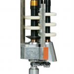
False twist spindle
1. auxiliary parts of draw texturing machine2. used for false twisting of PFY yarn
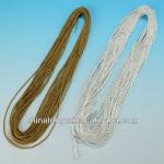
best double twister
double twister1-30mm
un-tube, ball or spool
for tomato packing
ISO, B.V.
DW7030H Simplex Flyer Frame
Simplex Flyer FrameDigital sample spinning system, absorb advanced technology and experience of domestic and foreign test yar
WJ130/5 wire mesh making machine
wire mesh weaving machine1.single electromotor driving
2.automatic compensation of wingding
3.automatic warp feeding

MADE IN CHINA WATER JET LOOM
1The product has applied for a patent2Good after-sales service system
3Best reputation in domestic market
4Computer contr

New water jet loom textile machinery
1.First-class Quality,first-class Technology2.One Year Guaranty
3.World-class after-sales service
4.Quick delivery
4 feed seamless rib knitting machine FL150
The rib knitting machine could achieve the plumule knitting, rib construction knitting and complex tissue knitting, with the rep
rcc pipe machine
rcc pipe machine1.obtain CE UL TUV ,CCC,EMC
2.cuts ,welds brazes and solders all known materials
3.cost effe
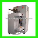
High Speed Polyester Spooler Machine
High Speed Polyester Spooler Machinetwo-for-one twister for filament
Twister
High reliability and outputTwo rope lays per revolution
Constant winding tension
Low power consumption
Easy maintenance
copper alloy fittings of textile manufacturing machine
textile machines fitting1)copper alloy
2)use for water-jet loom
3)10 years experience
4)welcome drawing or customer's idea